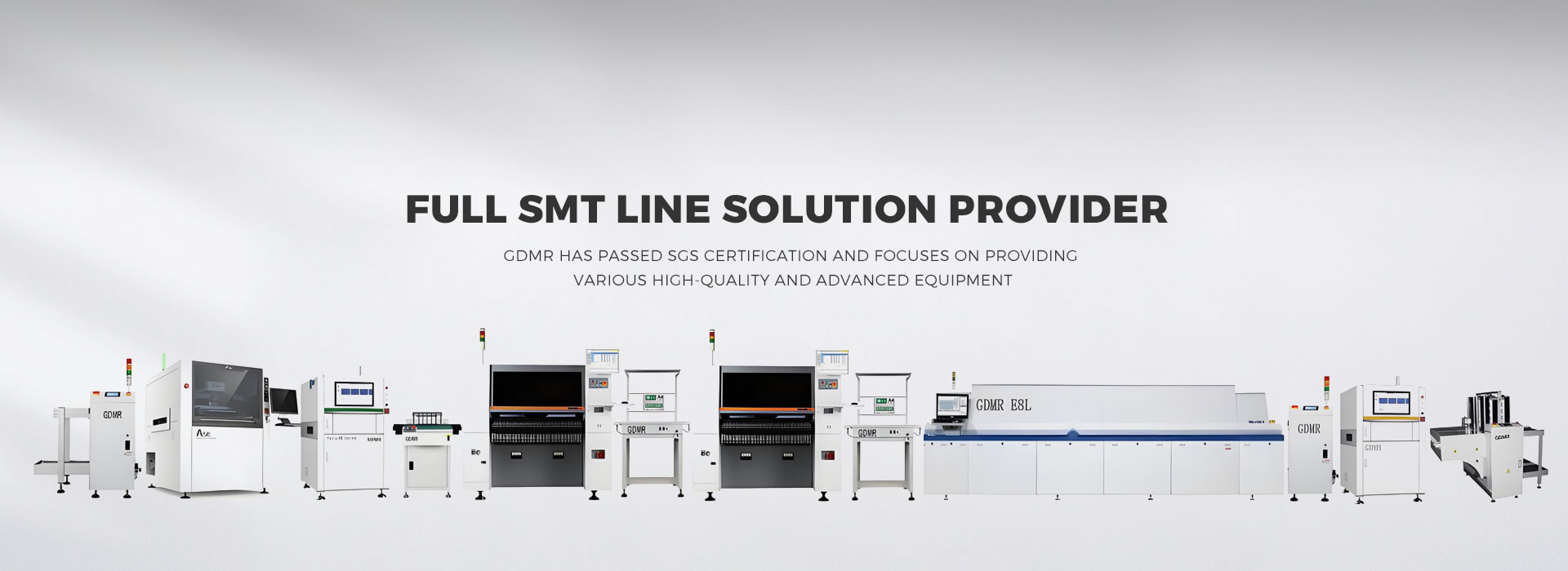
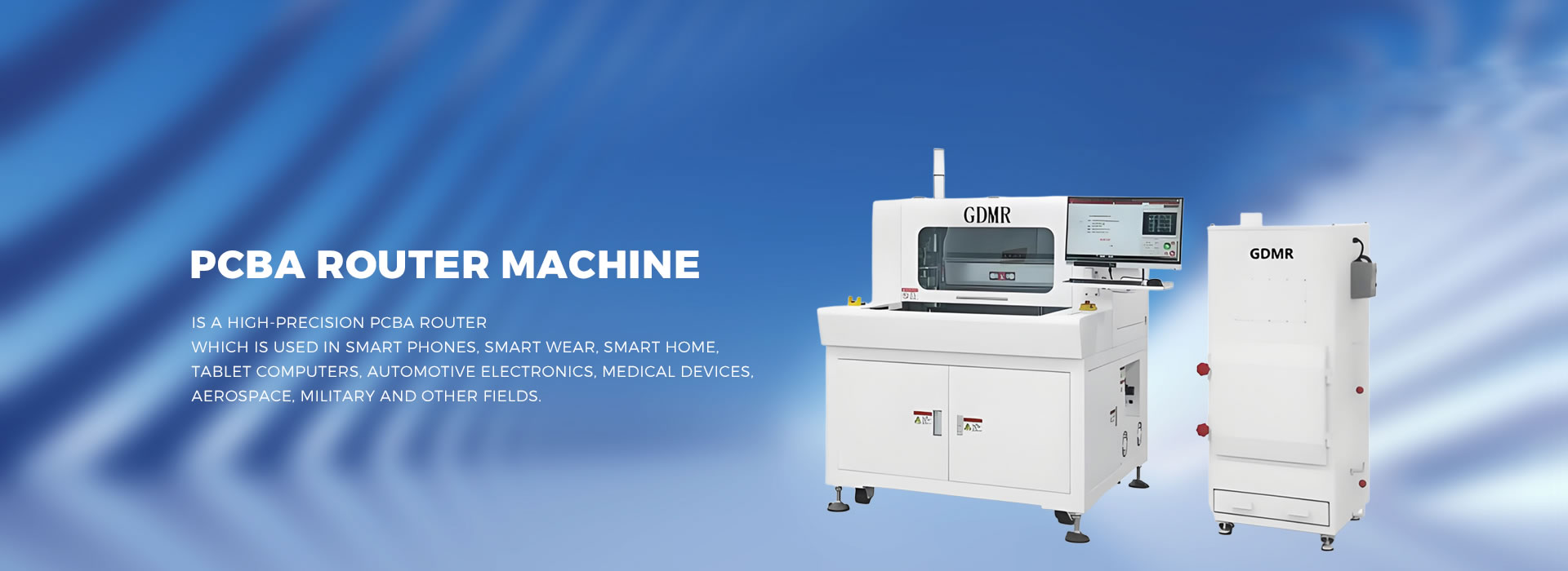
The cutting accuracy of PCBA cutting equipment is the core indicator to ensure the functional integrity and production yield of circuit boards. Its implementation depends on the comprehensive optimization of hardware design, software algorithms, process control, and environmental management. The following systematically explains how PCBA cutting equipment ensures cutting accuracy from three dimensions: key technology, process control, and environmental management:
1、 Hardware design: high rigidity structure and precision transmission system
Optimization of Machine Tool Rigidity
Whole cast bed body: Made of granite or aviation aluminum alloy, it is integrally formed to reduce the impact of vibration on the cutting path. For example, the bed stiffness of Schmoll equipment in Germany reaches 10 ^ 6 N/mm ², which can suppress resonance during high-speed milling.
Dynamic damping system: Integrated with air floating guide rails or hydraulic dampers, the vibration amplitude is controlled within ± 0.005mm to avoid cutting edge ripples.
Precision transmission components
Linear motor drive: replaces traditional ball screws to achieve nanometer level positioning accuracy (± 0.1 μ m). Like the Yaskawa linear motor in Japan, with an acceleration of 5g and a response time of<1ms.
High resolution encoder: uses a 25 bit absolute encoder (resolution 0.0001mm) to provide real-time feedback on the spindle position and eliminate accumulated errors.
Spindle system upgrade
Air bearing spindle: speed 60000-100000 RPM, radial runout<0.001 mm, suitable for micrometer level cutting. For example, the Swiss Precitec spindle has a lifespan of over 20000 hours and is more stable than ball bearing spindles.
Dynamic balance adjustment: By calibrating the spindle dynamic balance with a laser centering instrument, the unbalance is controlled within 0.1g · mm to reduce centrifugal force interference during high-speed rotation.
2、 Software Algorithm: Intelligent Path Planning and Error Compensation
CAD/CAM integrated system
DXF/Gerber file direct reading: Supports software such as AutoCAD and Altium Designer to output files, automatically recognizing cutting contours, V-grooves, and mark points (MARK points).
Path optimization algorithm: using genetic algorithm or ant colony algorithm to plan the shortest cutting path, reducing empty travel time by more than 20%, while avoiding overcutting caused by sharp turns.
Visual positioning and correction
High precision CCD camera: With a resolution of 5 million pixels, it can recognize MARK points with a diameter of 0.1mm and a positioning accuracy of ± 0.01mm.
Dynamic compensation technology: By collecting MARK point coordinates in real-time, comparing them with theoretical positions, automatically adjusting the cutting path, and compensating for PCB deformation (such as 0.1mm deviation caused by thermal expansion and contraction).
Power controlled cutting technology
Pressure sensor feedback: Install pressure sensors on milling cutters or laser heads to monitor cutting force in real-time (range 0.1-10N), adjust feed rate through PID algorithm, and avoid inconsistent cutting depth caused by pressure fluctuations.
Adaptive cutting depth control: Automatically adjust the cutting amount of the spindle according to the PCB material (such as FR-4, ceramic, metal) to ensure cutting through without damaging the underlying circuit.
3、 Process Control: Parameter Optimization and Process Monitoring
Tool/laser parameter matching
Milling cutter selection: Choose the tool diameter (Φ 0.8-3.0mm), number of teeth (2-4 teeth), and coating (TiAlN or DLC) based on the PCB thickness (0.6-3.2mm) and material. For example, when cutting 1.6mm thick FR-4 plates, it is recommended to use a Φ 1.5mm double-edged milling cutter with a speed of 40000 RPM and a feed rate of 1000 mm/min.
Laser parameter calibration: For UV laser cutting machines, it is necessary to optimize the wavelength (355nm), pulse width (10-20ns), and repetition rate (50-200kHz) to control the heat affected zone (HAZ)<0.05mm.
Cutting process validation
First Article Inspection (FAI): Before cutting, use a Coordinate Measuring Machine (CMM) to check the coordinates of the MARK point and confirm that the deviation from the CAD design is less than 0.02mm.
Online monitoring system: Integrated laser interferometer or laser tracker, real-time monitoring of cutting path deviation, automatic shutdown alarm when the error exceeds ± 0.03mm.
Waste disposal and cleaning
Vacuum suction system: Install multi-stage vacuum suction ports in the cutting area with a suction force of ≥ 0.8 bar to promptly remove debris and avoid edge burrs caused by secondary pollution.
Dust removal and filtration device: HEPA filter (efficiency 99.97%) is used to ensure that the dust concentration in the workshop is less than 0.5mg/m ³, and to prevent electrostatic adsorption from affecting accuracy.
4、 Environmental Management: Temperature, Humidity, and Static Control
Constant temperature and humidity workshop
Temperature control: Maintain 22 ± 1 ℃ to avoid dimensional changes in PCB caused by thermal expansion and contraction (0.02mm/m deformation caused by every 1 ℃ temperature difference).
Humidity control: Maintain 45-65% RH to prevent static electricity accumulation (static voltage can reach 10kV or above when humidity<30% RH).
Anti static measures
Grounding system: Equipment, workbench, and operator are grounded through a 1M Ω resistor, and discharge static current
Ion air gun: Blow the PCB surface before cutting to neutralize residual charges and avoid dust adsorption.